

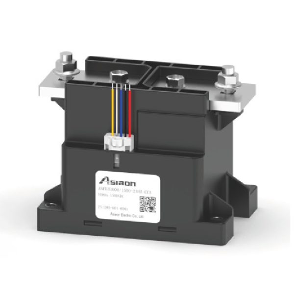
Product Features
- Ceramic brazing sealing technology; sealed chamber meets IP67 protection rating.
- Hydrogen-filled chamber effectively prevents oxidation of internal metallic components.
- 1000A continuous current carrying capacity
- 1 set of bridge-type normally open (SPST-NO) contacts; non-polarized main contacts.
- Widely applicable to construction machinery, energy storage systems (ESS), EV charging stations, and other electrical sectors.
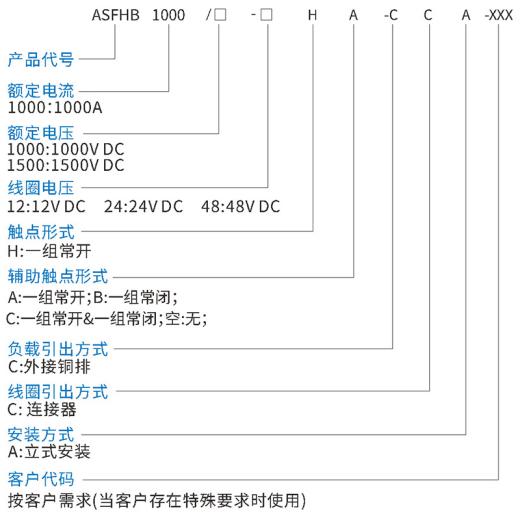
Model Description
Main Technical Specifications
| Parameters | Specifications |
| Contact Form | 1H (SPST-NO) |
| Rated Load Current | 1000A |
| Min. Load (Resistive) | 1A 12VDC |
| Max. Breaking Current | 3000A (1000V DC; 50ms; 1 op) |
| Max. Switching Voltage | 1500VDC |
| Contact Resistance (Initial) | ≤0.2mΩ@1000A (Initial) |
| Overload Current Capability (Conductor size XX mm²; 85°C) | 1000A cont. 1500A 200s 2000A 100s 3000A 16s |
General Electrical Characteristics
| Parameters | Specifications |
| Insulation Resistance (Between Open Main Contacts) | ≥1000MΩ(@1500VDC) |
| Insulation Resistance (Between Main Contacts and Coil) | ≥1000MΩ(@1500VDC) |
| Insulation Resistance (Between Main and Auxiliary Contacts) | ≥1000MΩ(@1500VDC) |
| Dielectric Withstanding Voltage (Between Open Main Contacts) | ≥5000V AC (1min; leakage current ≤1mA) |
| Dielectric Withstanding Voltage (Between Main Contacts and Coil) | ≥5000V AC (1min; leakage current ≤1mA) |
| Dielectric Withstanding Voltage (Between Main and Aux Contacts) | ≥5000V AC (1min; leakage current ≤1mA) |
| Operate Time (At rated coil voltage, 23°C) | ≤100ms |
| Release Time (At rated coil voltage, 23°C) | ≤30ms |
Auxiliary Contact Specifications
| Parameters | Specifications |
| Contact Form | 1H(SPST-NO) |
| Rated Load | 100mA 6V DC |
| Min. Load | 3mA 6V DC |
| Contact Resistance | ≤150mΩ@1A |
Shock & Vibration Resistance
| Parameters | Specifications |
| Shock – Stability (Disconnected) | 1/2 sine,11ms,20G |
| Shock – Stability (Closed state) | 1/2 sine,11ms,20G |
| Shock – withstand | 1/2 sine,6ms,50G |
| Random vibration | 10Hz~2000Hz,57.9m/s² |
Operating Conditions
| Parameters | Specifications |
| Ambient Temp | -40℃~+85℃ |
| Humidity | 5%~85%RH |
Endurance
| Parameters | Specifications |
| Electrical Endurance (Resistive) | Making |
| 100A/1000V DC 50 (ops) | |
| Breaking | |
| 1000A/1000V DC 300 (ops) | |
| 1000A/1500V DC 200 (ops) | |
| Mechanical Endurance | 20W ops |
Coil Characteristics (@23°C)
| Rated Voltage V DC | Max. Operating Voltage V DC | Pick-up Voltage V DC | Drop-out Voltage V DC | Power Consumption W |
| 12 | 16 | ≤9 | ≥1 | Inrush:50 |
| Holding:5 | ||||
| 24 | 32 | ≤18 | ≥2 | Inrush:50 |
| Holding:5 | ||||
| 24 | 63 | ≤36 | ≥4.8 | Inrush:50 |
| Holding:5 |
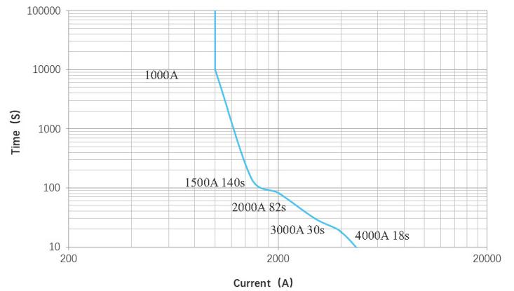
Current withstand curve
Notes:
1. Ambient temperature: 85°C; conductor cross-sectional area: ≥800 mm².
2. The upper temperature limit of the curve is 130°C, representing the maximum capacity for long-term cyclic operation.
3. In the event of short-term operation at currents ≥2000 A, there is a risk of the product components sticking (fusing) together; however, this will not result in fire or explosion.
4. The data in this curve is provided for design reference only. Final component selection and the matching of short-circuit protection fuses must be based on actual verification/testing.
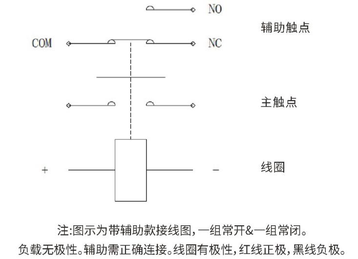
Wiring diagram
External dimensions (mm)
ASFHB1000/口-口HA-CCA
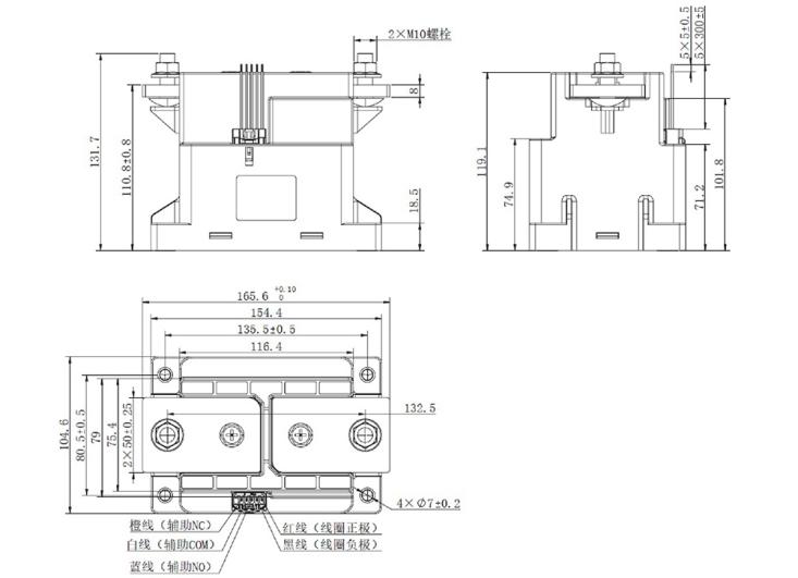
Note: Undimensioned tolerances for product outline dimensions:
| Size (mm) | <10 | 10~50 | >50 |
| Tolerance (mm) | ±0.3 | ±0.5 | ±0.8 |


Reviews
There are no reviews yet.